# Compiler Backend
Ola compiler backend bridge IR structure of module, function and Instruction Set Architecture(ISA) related callconv, registers and instructions. Its main features are code generation related lower and optimization related passes.
Target ISA mainly contains custom target instructions, registers which contain register class and register information, call convention and datalayout information.
Module in addition to inheritance IR is parsed out as Module structure, the description of its function and differ significantly with LLVM IR. Data information of Basic Block (BB) in the instructions target for the instruction, the register contains VRegs (Virtual Registers) and RegUnit (Register Unit) two categories, and contains a VRegs to Instructions (Insts) mapping. At the same time, instruction in data layout is referred to target instruction. Note that the structure of slot which contains stack base pointer and stack offset describe the memory access operations of parameters, local variables.
The lower provides the process of downgrading IR instruction to target instruction. Specifically it also requires copy parameters to VRegs for function call.
The pass module contains the register allocation (RegAlloc, RA) and spiller for analyzing the liveness of the pass and the function pass.
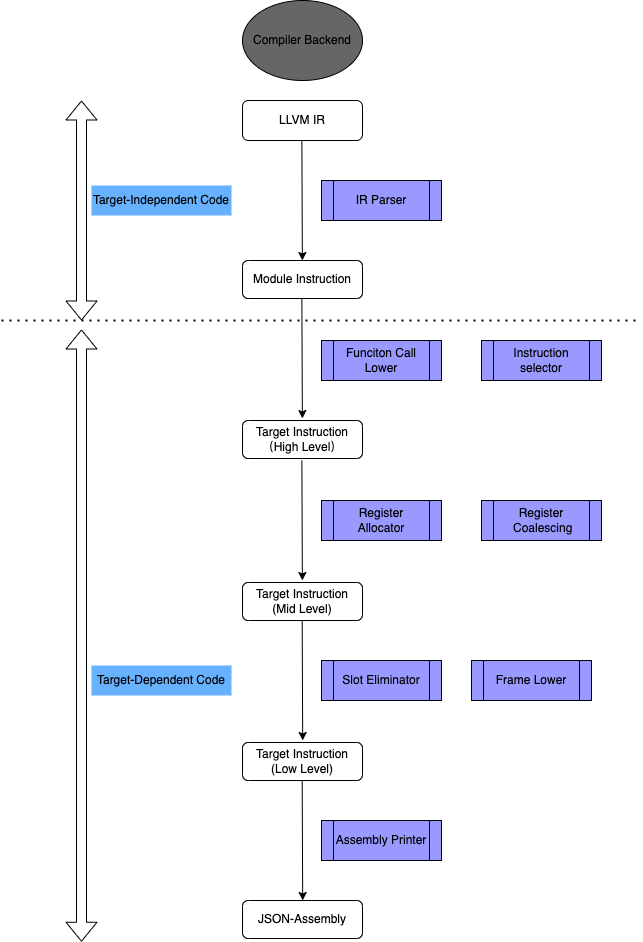
The backend of the Ola compiler compiles IR into target assembly code. It takes the standard LLVM IR generated by the frontend as input and the Ola assembly code as output.
Its pipeline process is as follows figure
ola compiler backend
## LLVM IR Parser
The role of IR parser is to parse LLVM IR to Module Instruction. Its parsing briefly process is as follows:
1. Parser parse target DataLayout and Triple, the result is target data information.
2. Parser parse attribute group, the result is attribute information of module.
3. Parser parse local types in module, the result is registered type in module.
4. Parser parse global variables, the result is global variables symbol table.
5. Parser parse function which is mainly divided into arguments list and function body, the result is function structure in module instruction.
6. Parser parse metadata, the result is metadata map in module.
## Optimizer: Optimization Passes on Parsed IR
Usually there are two kinds of compiler Optimization (Opt) passes, one is analysis passes and the other is transform passes. Currently our analysis pass is mainly Dominator Tree analysis pass, while transform passes contains Dead Code Elimination (DCE), Promote Memory to Register (Mem2Reg), Sparse Conditional Constant Propagation (SCCP).
## Register and Instruction
The register description is as follows:
| Type | Description | Register Group |
| -------------------- | -------------------------------------------------------------------- | ------------------ |
| general registers | General used by program | `[r0-r8]` |
| return register | Return value for return to caller | `[r0]` |
| parameters registers | Parameters value for passing arguments | `[r1, r2, r3]` |
| temporary registers | Temporary alloc for local variables | `[r4, r5, r6, r7]` |
| stack pointer | Function's stack pointer | `[r8]` |
| special registers | Interact with vm: pc for program counter and psp for prophet pointer | `[pc, psp]` |
## ABI Lower: Lowering Function Call
Ola Procedure Call Standard (OPCS) are as follows:
* The stack initialization points to the first address of the frame stack after the `fp` register is loaded.
* The address will be increased when the `call` instruction is executed later.
* When the `ret` instruction is executed, the `fp` register points to the address and falls back.
The Calling process is as follows:
* **call label**
Caller uses `call` instruction to call a callee as `call functionLabel`, and `fp` points to the new frame.\
The `pc` address returned by the callee is placed in `fp-1` which is detected by VM but not visible by the compiler backend.\
Its instructions pattern are as follows:
```assembly
main:
.LBL0_0:
...
call foo
...
foo:
.LBL1_0:
...
```
* **function address**
The address pointed to by `fp` before the function call is placed in `fp-2` as `mstore [r8,-2] r8`.\
Its instructions pattern are as follows:
```assembly
mstore [r8,-2] r8
```
* **passing arguments**
Function parameter processing: the first three input parameters are placed in the three registers `r1`, `r2`, and `r3`. If there are more than 3 parameters, start with the fourth input parameter and descend accordingly in `fp-3`, `fp-4`, `...`.\
Its instructions pattern are as follows:
```assembly
mov r1 vreg1
mload r2 [r8,offset]
mov r3 vreg2
```
* **local variables**
Local variables inside the function start at old `fp`, and their addresses are stored incrementally.
The single return value is stored in `r0`. If there are multi return values, it needs to be returned by a memory pointer that return the package data.\
Instruction pattern for single return value is as follows:
```assembly
mov r0 vreg3
```
The call stack frames layout is as follows (due to the limitations of Markdown, you cannot directly embed images, but you can link to them):
For prophet library functions, its instructions pattern as:
```armasm
.PROPHET{funcNum}_{prophetNum}: // bind to prophet label
mov r0 psp // interact with prophet read-only memory, getreturn value from prophet pointer
mload r0 [r0,0] // used returned r0 as indexed addressing
```
* First `.PROPHET` label binds to the prophet instance in assembly output.
* Then the program interacts with prophet read-only memory, get the return value from prophet pointer `[psp]` and write the result into `r0`.
* At last, we use `r0` as indexed addressing to load return values from prophet memory.
Please note that Markdown doesn't support referencing figures with labels as LaTeX does, so you'd typically just describe the figure and provide a link to it or insert it directly if the platform allows for image embedding.
## Instruction Selection Pattern
| Pattern Type | Description |
| ------------------ | ------------------------------------------------------------------------ |
| Alloca | params and vars allocation, selected to memory operations |
| IntBinary | binary operator |
| Load | memory load, containing base or offset |
| Store | memory store, containing base or offset |
| Call | A (caller) call B (callee) |
| Return | B (callee) return to A (caller) |
| Branch | branch control flow, selected to jump operations |
| Conditional Branch | conditional branch control flow, selected to compare and jump operations |
## Conditional Branch Selection Pattern
| Operator | Reg and Imm | Reg and Reg | Cycles |
| -------- | --------------------------------------------------------------------------------------------------------------------------------------- | -------------------------------------------------------------------------------------------------------------- | ----------------------------------- |
| == |
|
## Slot Elimination
This pass handles the stack slot for local variables.
Its pipeline is as follows:
```
VistModule
| VisitFunction layout
| VisitBasicBlock
| Match inst's data operand is Slot type
| workList: push inst
| Compute slot offset
| foreach workList
| fixup inst's operand with offset and size
```
## Register Allocation and Coalescing
Register allocation use linear scan method, its briefly steps as follows:
1. we analyze liveness in function, for input and output find live in and live out.
2. we insert spill and reload code, push it to worklist.
3. we rewrite the virtual register for the target register.
While the steps for register coalescing is as follows:
4. We traverse the `movrr` target instructions at basic block of function on the module.
5. If the two registers of operands are the same, then we push the instructions into the work list.
6. We can then remove the instructions in the work list from the function.
## Assembly Printing
The basic format of the Ola assembly language is as follows:
```plaintext
{symbol} {instruction | directive | pseudo-instruction} {; | // comment}
```
* **Symbol** indicates a symbol, which must start at the beginning of the line.
* **Instruction** indicates an instruction, it is usually preceded by two spaces.
* **Directive** indicates a pseudo operation.
* **Pseudo instruction** means a pseudo instruction.
* Directives, pseudo operations, and pseudo instruction helpers are all case-sensitive, but cannot be mixed.
### Assembly Instructions
For simplicity, pseudo operations and pseudo instructions like `.global` are not considered for now. Function entries that start with `funcName` and end with `:` are treated as a label. For example, `main:` defines a label for a function named main.
**Note:** The symbols that usually start with `.` indicate pseudo directives or pseudo operations, such as different segments. Symbols ending with `:` indicate labels, such as function names and basic block numbers.
### Instruction Format
The format of the internal assembly instruction is in the form of a three-address code:
```plaintext
```
* `Opcode` indicates the instruction helper, usually the instruction helper defined by OlaVM.
* `Rd` indicates the instruction operation destination register, which is usually the register defined by OlaVM.
* `Rn` indicates the first source operand of the instruction, usually a register defined by OlaVM.
* `shifter_operand` indicates the instruction data processing operand, usually an immediate or register defined by OlaVM.
### Memory Layout
After the program is loaded, `pc` points to the zero address and the function stack frame is switched according to the hierarchy of function calls, and the memory address stack grows from a low address to a high address. When prophets are present in the program, an indexed addressing register is required to interact with the prophet memory.